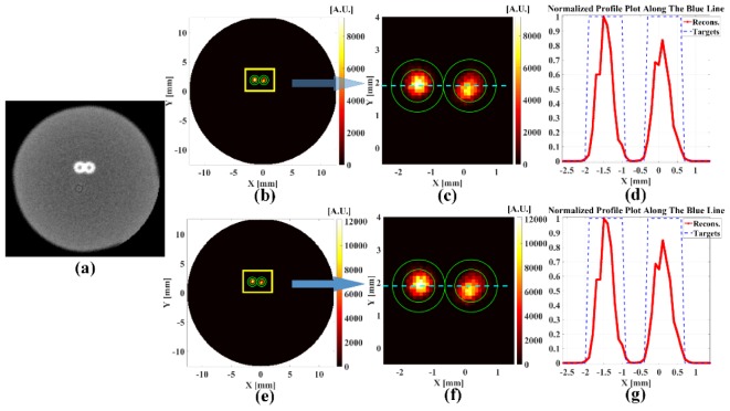
Fig. 14.
(a) A transverse section from the reconstructed microCT image of the phantom with two targets; (b) The reconstructed XCLT image with two parallel X-ray beams; (c) The zoomed in region in (b); (d) The normalized profile plot across the targets in (c); (e) The reconstructed XLCT image with two conical X-ray beams; (f) The zoomed region in (e); (g) The normalized profile plot across the targets in (f). The green circles are the inner and outer walls of the plastic tubes. The dotted line indicates the profile position.

