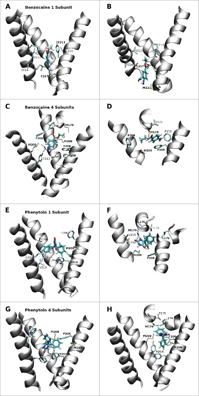
Figure 5.

Snapshots from the equilibrium simulations representing the 2 most favored positions of benzocaine and phenytoin in each system. While the full pore forming domain of NavAb (residues 115–221) was used in these simulations, for clarity, only selected residues from the S6 helices (residues 200–221) and the region between the S5 and S6 helices (residues 170–178) are shown in this figure. A and B: Benzocaine in the 1S system in the region of the activation gate. C and D: benzocaine in the 4S system with the amine oriented toward Y213 (C) and pi-stacking with F206 (D). E and F: phenytoin in the 1S system occupying the central cavity above Y213 (E) and in the fenestration (F). G and H: phenytoin in the 4S system with (G) the amine oriented toward Y213 while the benzyl rings are surrounded by the bulky residues M209, F206 and Y213; or (H) straddling F206 and with one benzyl ring protuding into the fenestration.
