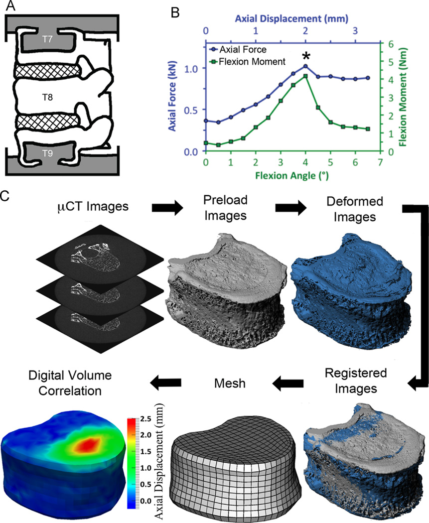
Fig. 1.
(A) Preparation of the T7–T9 spine segments (grey = PMMA; cross-hatch = IVD; white = bone); (B) Mechanical testing involved stepwise loading with a µCT scan performed at each loading step; the asterisk denotes the peak of loading, which was the loading step used for comparison of the measured and FE-computed displacements; (C) Experimental procedure for image processing in preparation for digital volume correlation; The output of the digital volume correlation are the displacements occurring throughout the T8 vertebral body, though only the axial displacements on the surface of T8 are depicted in the figure.

