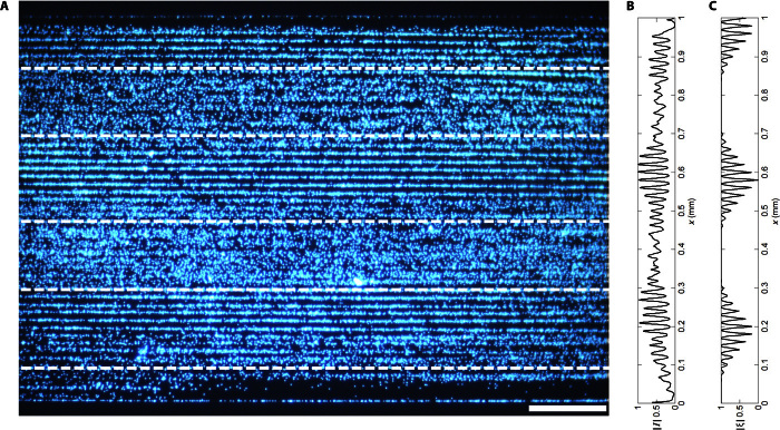
Fig. 4. Generation of multiple discrete patterning regions.
(A) The application of a 75-ns pulse with a 200-ns period, which is less than the minimum time it takes for a complete wave to pass across the 1-mm channel (the channel’s 254-ns TOF plus the 75-ns pulse period), generates symmetric standing wave regions as visualized with patterned 3-μm particles. (B and C) The measured mean intensity across the width of the channel (B), corresponding to the predicted locations of minimum time-averaged displacement (C). Scale bar, 200 μm.

