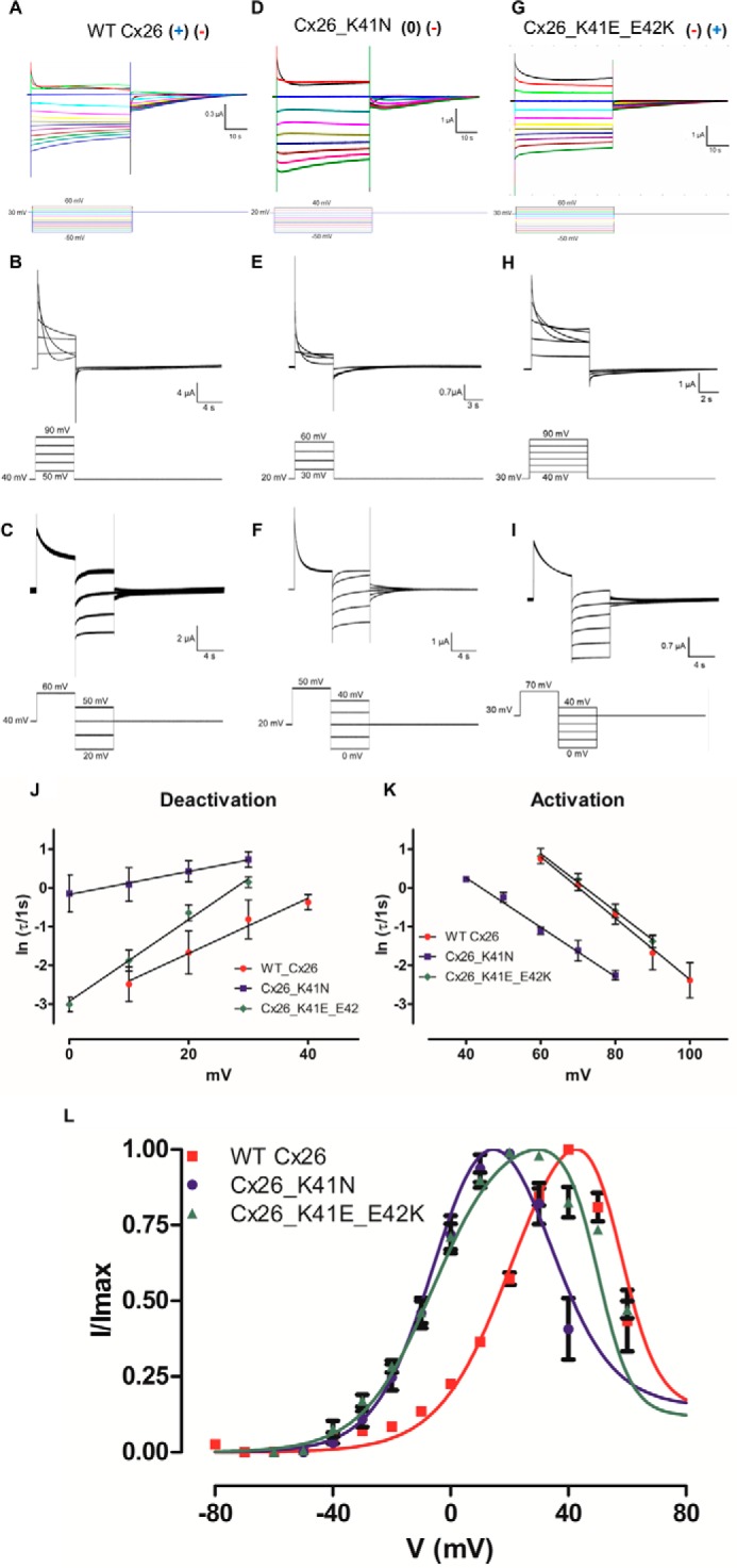
FIGURE 2.

Determination of voltage dependence in WT and mutant Cx26 hemichannels. Oocytes bathed in extracellular solution and maintained in a holding potential of +30 mV (WT Cx26 and Cx26_K41E_E42K) or +20 mV (Cx26_K41N) were subjected to voltage pulses from −50 to +60 mV (WT Cx26 and Cx26_K41E_E42K) or + 40 mV (Cx26_K41N), and returned to holding potential. The currents are shown for oocytes expressing WT Cx26 (A), Cx26_K41N (D), and Cx26_K41E_E42K (G). The I/Imax relation of WT Cx26 (red squares), Cx26_K41N (blue dots), and Cx26_K41E_E42K (green triangles) mutants are shown (L). To determine the voltage dependence of activation and deactivation of the fast gate, differential voltage protocols were applied. Oocytes were bathed in extracellular solution and maintained at a holding potential of +40 (WT Cx26) + 30 (Cx26_K41E_E42K) or +20 (Cx26_K41N) mV. To obtain the activation reaction rates for WT Cx26 (B), Cx26 K41N (E), and Cx26_K41E_E42K (H) squared positive voltage pulses from +50 to +90 mV (WT Cx26), from +30 to + 60 mV (Cx26_K41N), or from +40 to +90 mV were used. To obtain deactivation reaction rates for the WT Cx26 (C), Cx26 K41N (F), and Cx26_K41E_E42K (I) squared positive voltage pulses from +60 mV (WT Cx26), +50 mV (Cx26_K41N), or +70 mV (Cx26_K41E_E42K) were used to promote the population of the subconductance state, after which several negative voltage pulses were applied from +50 to +20 mV (WT Cx26) or from +40 to 0 mV (Cx26_K41N and Cx26_K41E_E42K). The current traces were fitted using an exponential decay function. The natural logarithm of τ versus voltage was plotted for the deactivation (J) and activation (K) of the fast gate. The voltage dependence of activation (α) and deactivation (β) was calculated from the slope of a linear regression of the data (straight lines, Equation 10 and 11), and the results can be seen in Table 2. To determine the voltage dependence of the slow gate, I(V)/Imax curve was fitted using Equation 6 (L). The parameters utilized for the fast gate were taken from the kinetic analysis, and the results can be seen in Table 3. Current traces and corresponding voltage traces have the same color.
