
Figure 10.
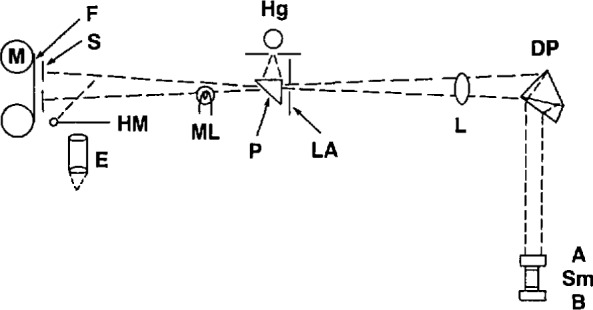
Schematic drawing of the recording interferometer [36,37,38]. A low-pressure electrodeless 198Hg lamp, Hg, provides light for the interferometer through a prism, P, a limiting aperture, LA, lens L, and a double dispersing prism, DP. The light is partially reflected by the lower surface of optical plate A and then fully reflected by the upper surface of plate B; the two plates enclose the sample, Sm, and with it create the interference fringe pattern that falls upon the narrow horizontal slit S and is recorded on 35 mm panchromatic film F. A hinged mirror, HM, and eyepiece, E, allow the operator to view the fringe pattern before recording it. A drive mechanism, M, moves the film at one of three pre-chosen rates. A marker lamp, ML, can be used to identify particular locations on the film. (Reprinted from reference [19].)