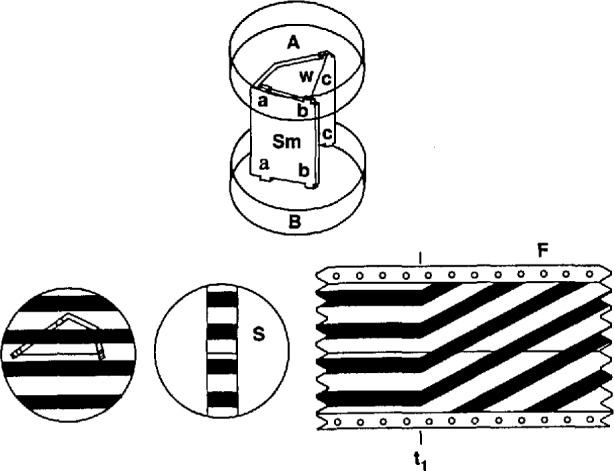
Figure 11.

Sample assembly and fringe pattern. The upper surface of the upper optical plate, A, makes an angle of 20° with respect to the lower surface, so that its reflections do not appear in the field of view. The lower surface is coated with TiO2 for 30% reflection. The upper surface of the lower optical plate, B, is coated for total reflection, while its lower surface was left rough. The sample, Sm, is shaped so as to provide three-point support for the upper plate. Three sets of tabs, a–a, b–b, and c–c were left on the upper and lower sample edges for fine adjustment of the plate separation, so as to produce a fringe pattern similar to that shown in the lower left corner of the drawing. The pattern is partially blocked by a slot S in the central copper tempering block, providing a filmed image that is fixed with respect to the fiducial wire, w, during steady-temperature recording. At time t1, the film, F, moving leftward, begins to record the moving fringe pattern resulting from a change in sample temperature. (Reprinted from reference [19].)
