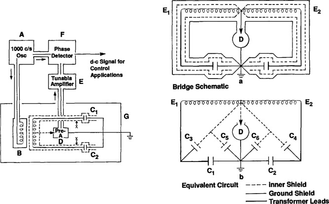
Figure 2.
Left side—Block diagram of the capacitance bridge used to match the mercury levels in the gas thermometer manometer. Right side—Capacitance bridge schematic, shown without the primary windings (upper drawing), and its equivalent circuit (lower drawing). E1, E2—voltages opposite in phase, and with a ratio that is fixed within I ppm of the turns ratio. C1, C2—active capacitor elements. C3, C4—minimized capacitance between the inner shield and the transformer leads. C5, C6—minimized capacitances between the inner shield and the ground shield. D—High-impedance detector. (Reprinted from reference [9].)

