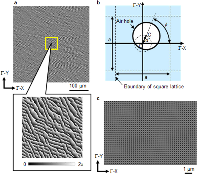
Figure 2. Phase-modulating resonator of the iPM laser.
(a) Phase distribution of the phase-modulating resonator, consisting of 1400 × 1400 points. The grayscale indicates the phase. The lower picture shows an enlarged view of the area outlined by the yellow square. (b) Schematic of the phase-modulating resonator. The rotation angle ϕ corresponds to the phase distribution at each point in (a). (c) Top-view scanning-electron-microscope image of the phase-modulating resonator before becoming covered. This picture corresponds to a part of the 1400 × 1400 air-hole array.

