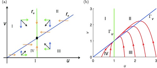
Figure 1.

(a) Directions of the vector field in the four regions I, II, III, and IV in the phase plane divided by the null clines Γu (green) and Γv (blue). Please refer to the text for description of the blue and green arrows. (b) Orbits in the phase plane for starting at where u(0) = 0.4, 0.8, 1.5, 2.0, 2.5, 3.0, and , as well as the null clines Γu (green) and Γv (blue) (MATLAB model code provided in Supplementary Figure S1).
