
Figure 2.
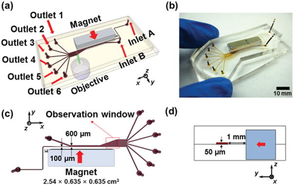
Device illustrations. a) Schematic drawing of the separation device with a permanent magnet and a microfluidic channel. b) An image of prototype device. c) Top-view of the device and relevant dimensions. Red arrow indicates direction of magnet’s magnetization. Red dashed box indicates the location of the observation window in Figures 4, 5, 6. d) Cross-section of the device. Red arrow indicates direction of magnet’s magnetization.