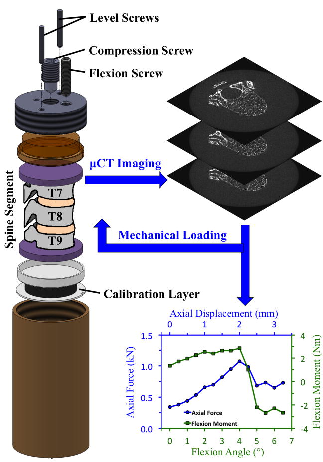
Fig. 1.
Schematic of radiolucent device for mechanical testing of spine segments under combined loading: The compression screw and flexion screw applied the axial compression and anterior flexion, respectively, at each loading step. The level screws ensured that the flexion angle was only applied in the sagittal plane. For compression loading, the flexion screw was not used, and the calibration layer was replaced with a load cell to measure the axial force. Details on the use of the calibration layer to measure the axial force and flexion moment during the combined-loading tests are provided in the Supporting Information (S2).

