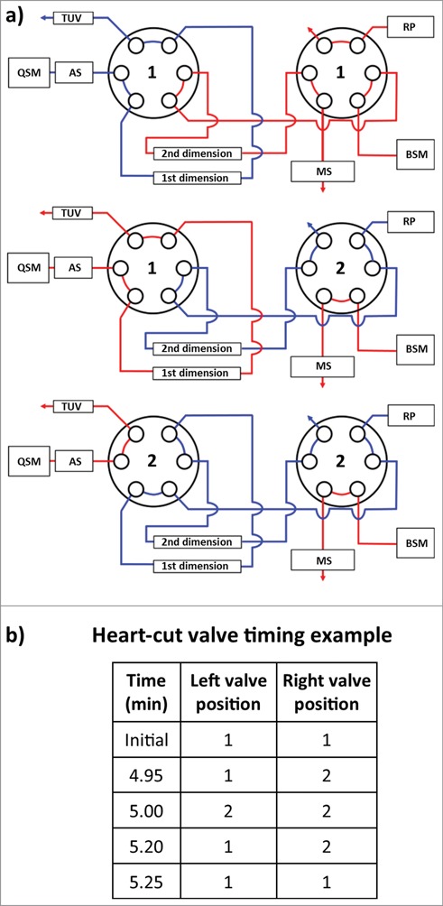
Figure 3.

Instrument configuration schematic. (A) A column manager housing two 6-port 2-position valves was configured as illustrated by the schematic to perform heart-cuts of the 1st dimension separation. Valve position is denoted numerically as position 1 and 2. Abbreviations are defined as QSM: quaternary solvent manager, AS: auto sampler, TUV: tunable ultraviolet detector, BSM: binary solvent manager, RP: regenerative pump, MS: mass spectrometer. (B) Heart-cuts were performed in 0.2 minute intervals at or near the apex of the peak under investigation. An example of the heart-cut being performed on peak (C) from Figure 5c is illustrated in the example. The heart-cut was bracketed with a 3 second interval to purge residual ammonium sulfate in the fluidic path post 1st dimension column.
