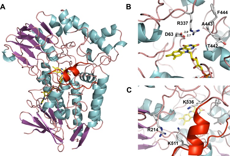
Fig 7. BVMOAFL838 crystal structure.
(A) Overall structure of BVMOAFL838 represented as a ribbon diagram with bound FAD as a stick model. “Variable” loop region covering the active site entry channel is shown in red. (B) Active site of BVMOAFL838 showing the catalytically important Arg (R337) and Asp (D63) and bulge-structure (T442-F444). (C) Substrate entry channel showing the “variable” loop structure in red and residue K511 from the “variable” loop within close proximity to the anticipated 2’-phosphate of NADPH. Also shown are residues (R214, K336) previously implicated in co-factor (NADPH) recognition and binding.

