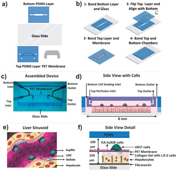
Figure 1.
Schematic of the various steps during fabrication of a two-chambered microfluidic device and the 3D co-culture assembly within the device. (a) Schematic of the four parts that were used to assemble the device. (b-1) PDMS-glass bond bottom chamber assembled firmly by using an air plasma treatment, (b-2) PDMS-PET membrane top chamber prepared at 70 °C using a PDMS coating and (b-3,4) assembly of the bottom and upper chamber. (c) Assembled microfluidic two-chamber device. The metal tubing shown is only used for illustration purposes and are not used during the experiments. (d) Side view of the device with the four cell types. (e) Cross-sectional schematic of the liver sinusoidal microanatomy. (f) Detailed side view of the assembled device with four cells, mimicking the microanatomy of the liver sinusoid.

