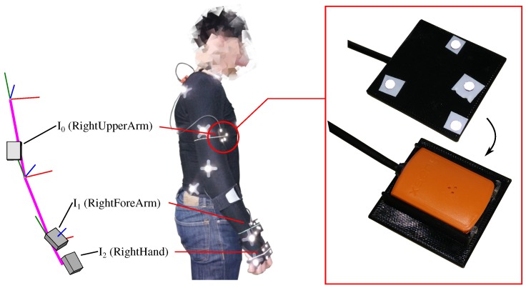
Figure 2.
Capturing setup for the real data scenario. In the picture on the left, the segment coordinate systems are associated to the proximal ends of the segments. Note, the axes are orthogonal and only roughly aligned with the anatomical axes of rotation through the skeleton fitting of the optical system as described in Section 2.6.1. Precise alignment with the anatomical axes was not in the focus of this study. In the N-pose, for the right arm, the x-axes are chosen perpendicular to the frontal plane pointing anterior, the y-axes are perpendicular to the transverse plane pointing along the segments in the direction from the distal to the proximal ends and the z-axes are perpendicular to the sagittal plane pointing lateral. The picture also indicates the initial arm configuration for real-slow and real-fast.

