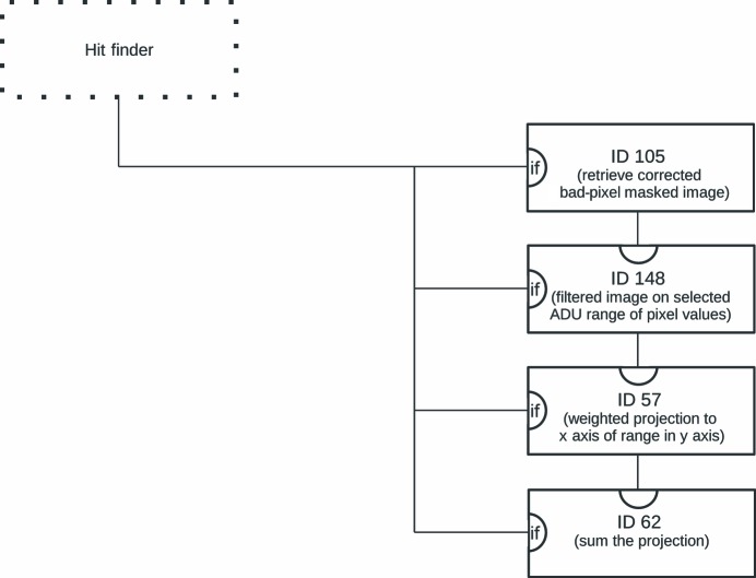
Figure 4.
Diagram to visualize that part of the .ini file that is responsible for extracting and processing the fluorescence information. Details are given in §4.1. The boxes are individual Processors with the indicated ID. The parentheses contain a short description of the purpose within the context. The dotted box indicates the section of the .ini file that determines whether the current image is a hit (see also §2.4). A line into the ‘if’ input of the box indicates that the Processor will only be run conditionally. A line into the top input indicates the input and the line going out at the bottom of a box represents the result of the Processor.

