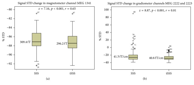
Figure 2.
Percentagewise standard deviation (STD) reduction in the signal latency range achieved by applying the SSS or tSSS methods in comparison to the level (at 0% STD) in the raw data recording without spatial filtering. The differences are shown for the amplitude peak channel of the magnetometers (a) and gradiometers (b) in Tukey box plots. Bold horizontal lines indicate medians, brown boxes indicate the first 50 percent of the case range, and vertical lines indicate cases within the 1.5 interquartile range from the edge of the 50% of the cases. Outliers more than 1.5 (circles) or 3.0 (stars) interquartile ranges from the edge of the 50% of the cases are denoted with circles or stars, and case numbers are provided for each outlier. The median values are shown in femtoteslas (fT) and femtoteslas per centimeter (fT/cm). z and r indicate the effect size, and p indicates the level of statistical significance.

