
Figure 14.
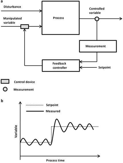
(a) Schematic structure of a feedback control loop. The deviation between the controlled variable and the specified set point is used to trigger and actuator action, adjusting the associated manipulated variable and compensating for the occurring disturbances. (b) Exemplary control action resulting in an overshoot reaction and oscillatory behavior during the set point changes.