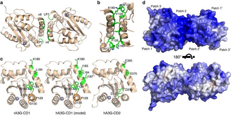
Figure 4. The dimerization of rA3G-CD1.
(a) The rA3G-CD1 dimer is formed through the interactions mediated by α6 and loop-7 (LP7). (b) Key residues critically involved in dimerization interface are shown in green sticks. (c) The locations of the key residues (green) for the CD1–CD1 dimerization on the surface of rA3G-CD1 (left) and the hA3G-CD1 (middle, modelled by rA3G-CD1 structure). The same orientation for hA3G-CD2 (3IQS15, right) is shown for comparison. The 128–130 KPD/DPD residues involved in Vif and A3G-CD1 interactions are coloured in orange. (d) Two views of the surface electrostatic potential of a rA3G-CD1 dimer, showing extensive positive charge (blue) on one side of the dimer. The top panel is the same orientation as in panel-a. The accessible surface is coloured by calculated electrostatic potential from −10 kT/e (red) to 10 kT/e (blue).

