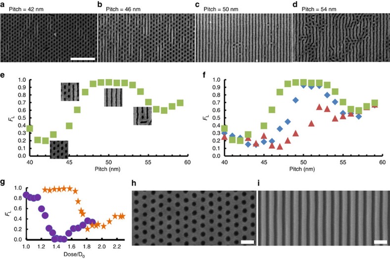
Figure 3. DSA of BCP blends on line gratings.
(a–d) Scanning electron microscope images of a 1:1 lamella:cylinder blend self-assembled on chemical line grating patterns with (a) 42 nm, (b) 46 nm, (c) 50 nm and (d) 54 nm using an electron beam exposure dose of D=1.1 D0 (where D0=1,600 μC cm−2) to define the chemical pattern. The white scale bar denotes 400 nm. (e) Fractional pattern area covered by lines FL, versus pitch of the underlying chemical prepattern for a single electron-beam dose D=1.1 D0. FL=1 denotes an entire pattern of lines, FL=0 is completely dots. (f) Fractional pattern area covered by lines FL versus chemical prepattern pitch for different electron-beam prepattern doses, 1.1 D0 (green squares), 1.2 D0 (blue diamonds) and 1.3 D0 (red triangles) (where D0=1,600 μC cm−2). For a given grating pitch, as we increase the dose, the resulting oxide stripes are wider. The process is optimized by selecting two pitches preferential for forming lines or dots and varying the dose. (g) FL versus dose for prepattern pitch of 46 nm (purple circles) and 50 nm (orange stars). Parameters can be independently selected for FL=0 or 1 in a single exposure. In h and i, we utilize the optimal SiO2 width and pitch to select from the blend a single morphology, aligned and nearly defect-free overextended areas.

