Fig. 4.

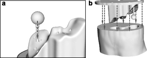
Schematic illustration indicating how lesion and support rods are placed within the phantom base (a) and how the base is fitting into the main phantom body (b)

Schematic illustration indicating how lesion and support rods are placed within the phantom base (a) and how the base is fitting into the main phantom body (b)