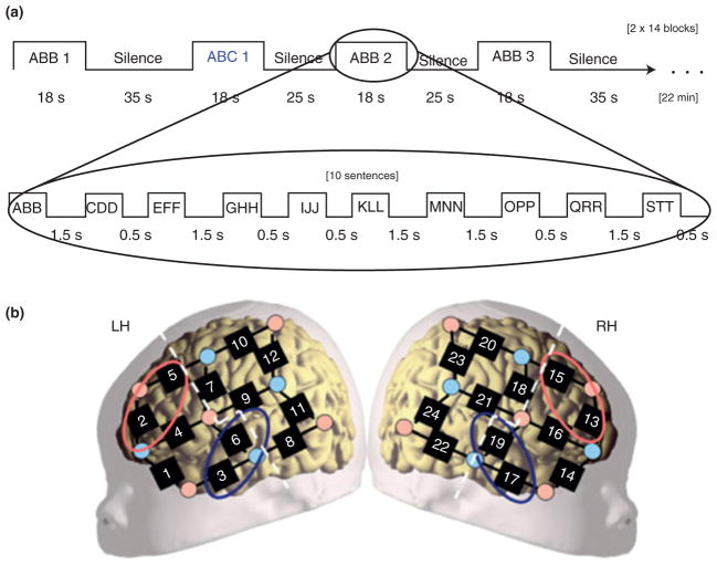
FIGURE 10.
Details of the procedure used by Gervain et al.10 (a) The experiments’ design. The upper boxcar shows how the consecutive stimulation blocks unfold. The lower boxcar indicates the sequence of sentence types within a block. (b) The placement of the probes overlaid on a schematic neonate brain. Although individual variation cannot be excluded, this placement ensured recording from perisylvian and anterior brain regions. The dashed white lines separate anterior and posterior ROIs. The red ellipses indicate the channels included in the frontal area of interest (LH: channels 2 and 5; RH: channels 13 and 15). The blue ellipses indicate channels included in the temporal area of interest (LH: channels 3 and 6; RH: channels 17 and 19). (Reprinted with permission from Ref 10. Copyright 2008 National Academy of Sciences).

