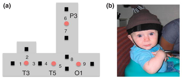
FIGURE 3.
The headgear used by Wilcox et al.56 (a) Configuration of the emitters (red circles) and detectors (black squares), and the nine measurement channels, in the headgear. Emitters were placed relative to 10–20 coordinates of the International 10–20 system (Figure 4). All the emitter-detector distances were 2 cm. Each detector read from a single emitter except for the detector between T3 and T5, which read from both emitters. The light was frequency modulated to prevent ‘cross-talk’. O1 lay over occipital cortex, T5 over posterior temporal cortex, T3 over anterior temporal cortex, and P3 over posterior parietal cortex. (b) Infants sat in a supportive seat to restrain excess movement. An elasticized headband was slid onto the infant’s head and secured by a chinstrap.

