

Abstract
Cardiac catheterization with ultrasound (US) imaging catheters provides real time US imaging from within the heart, but manually navigating a four degree of freedom (DOF) imaging catheter is difficult and requires extensive training. Existing work has demonstrated robotic catheter steering in constrained bench top environments. Closed-loop control in an unconstrained setting, such as patient vasculature, remains a significant challenge due to friction, backlash, and physiological disturbances. In this paper we present a new method for closed-loop control of the catheter tip that can accurately and robustly steer 4-DOF cardiac catheters and other flexible manipulators despite these effects. The performance of the system is demonstrated in a vasculature phantom and an in vivo porcine animal model. During bench top studies the robotic system converged to the desired US imager pose with sub-millimeter and sub-degree-level accuracy. During animal trials the system achieved 2.0 mm and 0.65° accuracy. Accurate and robust robotic navigation of flexible manipulators will enable enhanced visualization and treatment during procedures.
I. Introduction
Cardiac catheterization is useful for performing a variety of diagnostic and interventional tasks in minimally invasive procedures [1]. A robotic system for automatically steering cardiac ultrasound (US) imaging catheters can provide enhanced imaging of cardiac structures and working instruments. However, navigation in the vascular environment is difficult due to many inaccuracies, nonlinearities, and disturbances. Compensating for these environmental factors and enabling autonomous motion has the potential to improve clinical outcomes, save time, and ease the mental and physical burdens on clinicians.
Existing commercially available solutions for robotic catheter steering have focused on teleoperation, which enables the clinician to manipulate the catheter at a safe distance from the X-ray radiation used for visualization [2]–[6]. The clinician teleoperating the catheter can compensate for targeting errors. Automated flexible manipulator motion in constrained bench top environments has been demonstrated by research prototypes [7]–[12]. These prototypes have not been shown to steer accurately in the unconstrained environments typical of catheter interventions, and do not control the orientation of the manipulator tip, which is crucial for US imaging. Additionally, most are configured to steer custom built manipulators that are designed for robotic control; however this approach does not translate to clinical use as readily as a system that can robustly manipulate commercially-available catheters.
In our previous work we developed a system for automatically pointing cardiac imaging catheters in a constrained bench top environment [13]. While this system has proven to be effective for bench-level steering, it was necessary to implement a more robust controller that can cope with the friction, backlash, and unconstrained catheter shaft motion that occurs during in vivo procedures. The following sections of this paper describe motivation for redesigning the controller for improved robustness, the new control strategy, system characterization experiments, and results from in vivo catheter steering. This work provides the first method known to the authors for accurately controlling unconstrained flexible manipulators in the presence of unmodeled external disturbances.
II. Background
A. Ultrasound Catheters
While we focus this investigation on US catheters for cardiac procedures, our approach applies to general flexible steerable manipulators. Catheters are long, thin plastic tubes which are controlled at the proximal end outside the patient. US catheters use a transducer in the distal tip to acquire US images of tissue structures and instruments inside the patient. Typically inserted into the vasculature via the groin, the distal tip can be guided to organ systems such as the internal chambers of the heart. US catheters can provide high resolution views of anatomical structures and other instruments, but manually pointing the imager at a target requires significant training and skill.
The clinician manipulates the US catheter by holding the plastic handle and actuating four degrees of freedom (4-DOF), as seen in Fig. 1, to create the resulting tip motions in Fig. 2. The catheter handle can be translated (inserted/retracted) or rotated. Four pull wires, which are spaced apart 90° along the cross-section of the catheter shaft, connect the distal end of the catheter to two knobs on the handle. Each bending knob is connected to a pair of opposing pull wires. The distal end is less rigid than the rest of the catheter shaft such that the deflection of the pull wires causes moderate bending through the shaft and significant bending at the 5 cm distal ‘bending section’. The US transducer (64-element 2D US) is in the most distal 2 cm section of the tip. AcuNav is the most commonly used intracardiac US catheter at present (AcuNav, Biosense Webster, Diamond Bar, CA, USA). In this study the 8 Fr catheter (ø2.67 mm) with length 90 cm was used to validate the system.
Fig. 1.
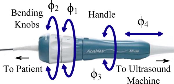
AcuNav US imaging catheter handle showing control DOFs.
Fig. 2.
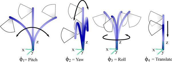
Joint inputs and corresponding tip motions.
B. Constrained Catheter Motion
In our previous work, the robotic system for steering cardiac imaging catheters relied on a set of physical constraints that isolated the bending to only the distal 5 cm bending section of the tip [13]. The base of the bending section was fixed with respect to the catheter handle and robot. This catheter tip fixation succeeded in isolating the bending section of the catheter and simplified the control required for steering, which was necessary at the beginning stage of our investigation of catheter position and orientation steering.
C Unconstrained Catheter Motion
Accurately maneuvering the 4-DOF catheter in vivo requires a controller that is robust to a number of inaccuracies and disturbances, which have been minimally addressed in the robotic flexible manipulator literature. Inside the plastic off-the-shelf catheter handle, slack pull wires connected to each bending knob exhibit large backlash regions that are non-linearly coupled to the rotations of both bending knobs (this relationship was examined in [13]). Additionally, the long catheter shaft experiences compression, bending, and torsion in the vasculature. This reduces the effectiveness of the bending knobs, increases friction between the catheter and the vascular walls, and causes the location of the base of the bending section to vary, as portrayed in Fig. 3. Here the catheter is shown in three potential configurations. The proposed controller keeps the tip at the target location regardless of where the base is located. The uncontrollable motion of the base point during unconstrained bending significantly affects the ability of the catheter to converge to the desired pose. To illustrate typical base motion, Fig. 4 shows the uncontrollable motion of the bending base during catheter tip navigation of a square trajectory with the shaft unconstrained. The range of displacements of the bending base in the xyz-axes were measured as [8.4 mm, 6.4 mm, 5.9 mm] and the maximum angular deviation from the centerline was 9.65°.
Fig. 3.

Uncontrollable catheter shaft motion. Dashed lines show alternative locations of the catheter shaft due to uncontrolled motion within the vasculature. EM trackers measure the position and orientation of the catheter at two locations: at the base of the bending section, and at the tip.
Fig. 4.
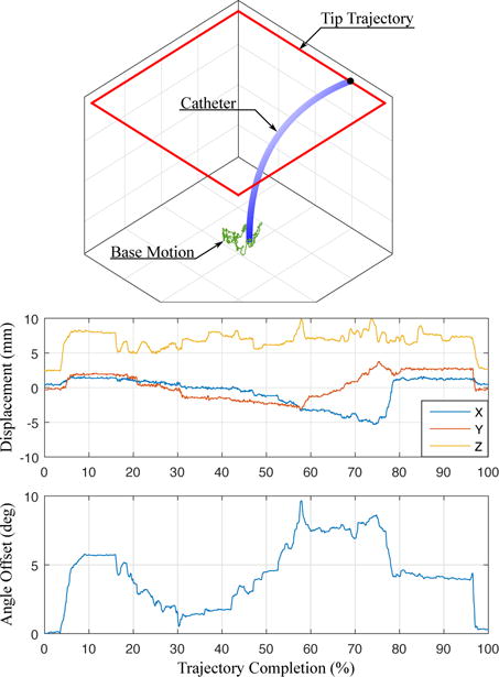
Catheter navigation causes uncontrollable motion of the bending section base. (top) The base motion is measured (green) while the catheter tip is navigated along a square trajectory (red). (middle) The displacement of base point in xyz coordinates and (bottom) the change in base point rotation about the catheter axis are measured.
The catheter passes into the patient vasculature through an introducer, which is a plastic tube containing a rubber seal to prevent blood outflow. Friction in the introducer seal increases backlash in catheter rotation and increases the amount of catheter buckling during insertion. Respiratory and cardiac motions of the patient also contribute disturbance to the system, resulting in further inaccuracies. Patient vasculature is highly variable in diameter, stiffness, curvature, and length. Catheter translation is subject to backlash as the catheter body conforms to the near wall or the far wall of the vasculature (examined in [14]).
While some of these effects may be avoided by altering the mechanical design of a catheter, it is less expensive and more clinically feasible for a robust controller to manipulate an off-the-shelf catheter. The following section describes a control strategy that will robustly converge the catheter tip to the desired position and point the US imager in the desired direction despite these effects and disturbances.
III. Catheter Kinematics
Previous research has mainly focused on 3-DOF continuum robot kinematics and did not consider the extra DOF required to control the heading of the US imaging plane [7]–[12]. Our kinematics derivation follows the methodology in [8]. With the use of two sensors (one at the tip and one at the base of the bending section (Fig. 3)) we extend this to enable 4-DOF control of US imaging catheters.
Three different parameter spaces are used to control the flexible manipulator: joint, configuration, and task space. The joint space is the four actuator variables, pitch (ϕ1), yaw (ϕ2), roll (ϕ3), and translation (ϕ4) shown in Fig. 1 and 2. The configuration space variables (d, γ, θ, α) describe the shape of the catheter as shown in Fig. 5. Lastly, the task space describes the position of the catheter tip (x, y, z) and orientation of the imaging plane (ψ). The mapping from joint space to configuration space is based on the mechanical design of the robot and the manipulator, and is therefore system-specific; whereas the mapping from configuration space to task space is a kinematic mapping that is broadly applicable to flexible manipulators.
Fig. 5.

Symbolic representation showing D–H parameters: translation, d, catheter handle roll, γ, bending plane angle, θ, bending angle around the global z-axis, α, length of the bending section, L.
The accuracy of the mapping between configuration space and task space is based on the following idealized assumptions: the bending section of the catheter has a constant curvature along its length (circular arc); the bending catheter lies on a single plane; and the effects of torsion about the catheter tip are negligible. In reality, these assumptions lead to less accurate results. However, the idealized relationships between task space and configuration space can still provide valuable information regarding how the robot joints should be adjusted for the catheter tip to reach the desired pose.
A. Forward Kinematics
Forward kinematics map the configuration space to task space. The table in Fig. 5 shows the D–H parameters. Frame 0 is the base frame, and Frame 7 is the catheter tip. Fig. 5 shows the configuration parameters, where d is the translation, γ is the catheter handle roll, θ is the angle between the x-axis of the catheter handle and the bending plane, and α is the bending from the global z-axis (i.e. the catheter body). L is the length of the bending section. The transformation matrix, T(d, γ, θ, α, L), describes the pose of the catheter tip in base coordinates (Eq. 1).
| (1) |
B. Inverse Kinematics
The idealized mapping from task space to configuration space begins with T and calculates α, d, θ, and γ. From the translational component of T we can calculate the distance from the catheter tip to the global z-axis as
| (2) |
where α ∈ ℝ+, cα denotes cos α, and ‖ · ‖2 is the l2-norm. Then α can be calculated by computing the root of the nonlinear equation in Eq. 2. The idealized d is then calculated from T34. The idealized angle θ is
| (3) |
Lastly, the angle γ can be calculated from
| (4) |
C. Joint Mapping
The desired configuration space motion can be mapped to the corresponding joint space inputs as
| (5) |
| (6) |
| (7) |
| (8) |
where Rc is the radius of the catheter body and Dknob is the diameter of the pulley inside the catheter handle.
IV. Control Strategy
The measured sensor information and idealized kinematic relationships are used together to calculate the joint space adjustments for tip convergence. The robot navigates the tip of the US catheter to reach the desired position while aiming the US imager in the desired direction by the controller in Fig. 8. It is not possible to control the full 6-DOF pose of the US imager, therefore the controller aims to adjust the 3-DOF position of the tip and the 1-DOF rotation of the US imager about the axis of the catheter tip.
Fig. 8.

The controller (gray box) receives the desired catheter tip pose and iteratively calculates joint angle adjustments to manipulate the catheter.
Two EM sensors are used to resolve the configuration of the catheter tip. One sensor is placed at the tip of the bending section, proximal to the US transducer such that the US beam is not distorted. The second sensor is placed at the base of the bending section to resolve physiological disturbances from the environment and the unmodeled behavior of the catheter body.
Let Tsensor be the transformation corresponding to the sensor reading at the current location of the catheter tip. The US imaging plane is the plane formed by the x- and z-axes of the tip pose. US imager rotation is measured in rotation of the x-axis about the z-axis of the tip pose. Tsensor cannot be directly used in the inverse kinematics calculations since the rotational component of the sensor reading will have rotations that are induced by the unmodeled effects in the system; instead a kinematically feasible configuration Ccurr = [dcurr,γcurr,θcurr,αcurr] needs to be calculated based on the position [xsensor, ysensor, zsensor], and handle roll γsensor reported by the base sensor. Let Ccurr = [dcurr, γcurr, θcurr, αcurr] represent this kinematically feasible configuration, with pose Tcurr.
The user indicates a desired position and change in heading, Xdes = [x, y, z, Δψ]. Calculating the desired catheter configuration, Cdes = [ddes, γdes, θdes, αdes], requires additional steps beyond using the inverse kinematics equations. Any change in catheter tip position induces a change in the imager heading that is dependent on the current and target positions. In order to arrive at the desired heading, this induced angular change ψinduced has to be calculated.
Calculate inverse kinematics given Xdes,xyz and the current handle roll, γcurr. The angle γcurr is measured from the base sensor (rather than the current roll joint) because a significant amount of rotation is lost through torsion along the catheter shaft. This calculates the configuration at the target, given γcurr. This pose is defined as Ttemp, and the configuration parameters are labeled as Ctemp = [dtemp, γtemp, θtemp, αtemp].
- The position and curvature of the catheter at the temporary and desired configurations are equal. Therefore, the configuration parameters ddes = dtemp and αdes = αtemp. However, the temporary pose only represents the target position and requires additional roll calculations to point the US imager (Fig. 6). We begin by calculating the angle between the x-axis at the temporary pose and the x-axis at current pose. This is done by first projecting to the plane defined by the vectors and ,
and calculating the angle ψinduced between the x-axes,(9)
To maintain directionality, we calculate the direction of the normal to the plane defined by and ,(10)
If ξ < 0 then the angle ψinduced is negated.(11) - At this point, we can point the US imager in the target direction by calculating the desired configuration parameters γdes and θdes as
(12) (13)
Fig. 6.
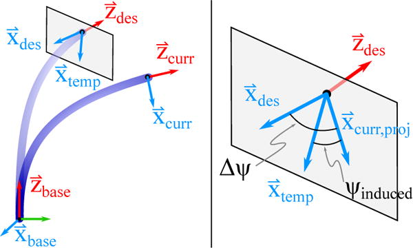
The required configuration space roll adjustments is calculated by projecting the axis on to the x – y plane of the desired coordinate frame.
The desired configuration is then related to the control inputs, ϕ1–4. Convergence to the desired pose is an iterative process, in which the tip of the catheter is sensed, and the remaining relative change required to reach the desired pose is recalculated. Image collection is triggered when the user-defined allowable translational and rotational error thresholds of the tip are satisfied.
A. External Disturbance Rejection
During in vivo procedures the catheter additionally experiences external disturbances due to respiratory motion, adjacent catheter motions in the same vessel, tissue motion due to displacement of adjacent organs, etc. We represent external disturbances as Uext in Fig. 8. Uext can cause the catheter shaft to translate (Fig. 7 left) and/or rotate (Fig. 7 right). Our controller needs to be robust to this external input such that stability is guaranteed and the catheter tip does not diverge from the target location.
Fig. 7.

Disturbance analysis. Disturbances in the base location of the bending section can cause (left) translations and/or (right) rotations, which can lead to the target exiting the workspace. The workspace of the US catheter is a cylinder, shown with dotted lines. The gray and black workspace cylinders correspond to the workspace before and after uncontrolled base motion. The tip of the catheter bends along the trajectory shown in orange. The blue dotted line represents the shortest distance between the target and the z-axis of the catheter base.
The workspace envelope of the catheter is a cylinder (Fig. 7). An external disturbance can move the base of the catheter so that the target point is no longer contained in the workspace. The condition for the target to remain within the workspace is to maintain ‖xdes, ydes‖2 ≤ Rw, where Rw is the radius of the workspace cylinder. Calculating the workspace boundary from the base tracker pose enables realtime detection of out-of-workspace errors. In the clinical setting, such errors would stop catheter servoing and be reported to the clinician for repositioning the catheter. The following two sections examine the response of the robotic system in the presence of external disturbances.
V. Experimental Methods and Results
A. Robot Design
The kinematic algorithms were implemented and tested on a robotic prototype for manipulating an US catheter. The design of the robot (Fig. 9) connects four actuators with the four DOF of the catheter handle. Robot motion accuracy was reported in [15], [16]. A system of coaxial rotating rings mates to the bending knobs and the catheter handle to actuate pitch, yaw, and roll. The rotational transmission rests on a linear stage which is translated by a lead screw. The robot was designed such that an US catheter can be quickly fastened into (and removed from) the robot during clinical procedures. Two lifts adjust the inclination of the robot for aligning the catheter with the introducer to minimize buckling of the catheter shaft.
Fig. 9.

US catheter manipulation robot prototype.
Each DOF of the robot is actuated by a brushless DC motor controlled using digital positioning controllers that run internal servo loops at 1 kHz. The error between the commanded and measured joint angle motion was negligible [15], [16].
The tip of the catheter is sensed by two 6-DOF electromagnetic (EM) trackers (trakSTAR, Ascension Technology/NDI, Ontario, Canada). The EM trackers have resolution of 0.5 mm and 0.1°, and RMS accuracy of 1.4 mm and 0.5°. The bench top and in vivo cathlab settings were designed for low magnetic interference. The base of the bending section is 85 cm distal to the base of the catheter at the handle.
B. Bench Top Motion
In preparation for in vivo studies, the performance of the controller was tested in a simulated vasculature environment on the bench top. The catheter was introduced through a 14 Fr introducer into to a smooth-walled plastic tube (Teflon FEP, 1.3 cm inner diameter, 62 cm length). The distal bending section of the catheter was able to bend freely outside the distal end of the tube.
The first bench top motion study measured the ability of the robotic system to navigate the catheter tip through space along a 4 cm square trajectory of 80 setpoints. The catheter was navigated through multiple trajectory orientations and sizes. The US imager was adjusted to point in the same heading for all trials. An example trajectory is shown in Fig. 10, where the blue line is the target trajectory and the red line is the measured trajectory of the catheter tip. The catheter tip reached the desired set points with mean errors 0.92 mm (σ = 0.12 mm) and 1.01° (σ = 1.05°). The base tracker moved up to 8.4 mm away from the initial point. The average time to navigate to each set point (dependent on the allowable error threshold and the proportional controller gain) ranged from 1.5 – 3.7 s, which is well within a 5 s specification for breathing motion.
Fig. 10.
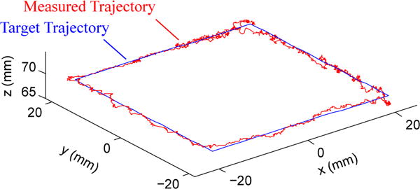
The catheter navigates a 4 cm square trajectory of 80 set points while pointing the US imager in the same direction for all points.
The next motion study isolated US imager rotation while maintaining a fixed position in space. The US imager was commanded to rotate 2° a total of 20 times with a specified allowable angular error threshold, while the position of the catheter tip was maintained within the 1 mm position error threshold (measured error mean 0.83 mm, σ = 0.3 mm). The average time to converge on the target imager heading ranged from 2.61 s (σ = 2.67 s) with error threshold 0.25° to 1.81 s (σ = 1.15 s) with error threshold 1°.
The last bench top study examined the performance of the system in response to a step disturbance. This is important because interaction with adjacent catheters can displace the shaft, and respiratory motion causes the heart and the supporting vasculature to shift. A step input disturbance was created by moving the vasculature phantom at the base of the catheter bending section, thereby displacing and slightly rotating the base of the catheter. The controller senses the disturbance and makes the necessary adjustments to converge back to the original target position and US imager direction. An example disturbance response test is shown in Fig. 11. The system was disturbed by moving the plastic tube before data collection. At t = 0 s the controller was activated and the catheter converged to the target pose. Data collection began at t = 5 s when the disturbance was removed (Fig. 11 (top)), causing a disturbance step input to the base of the bending section. This disturbance moved the catheter tip to the wrong pose (Fig. 11 (middle, bottom)). The controller then navigated the catheter tip back to the target pose. At t = 17 s the user commanded a Δψ = 2° imager rotation (a target step input), changing the desired imager angle from 0° to 2° and maintaining the position at 0 mm from the target. The tip converged to the target pose with mean errors 0.5 mm (σ = 0.3 mm) and 0.18° (σ = 0.12°).
Fig. 11.

Bench top tests demonstrating the ability of the robotic system to maintain the catheter tip at the target pose despite disturbance step and target step inputs.
C. In vivo study
In vivo animal testing was performed on a 55 kg porcine model due to anatomical similarities between porcine and human cardiac anatomy. To create a repeatable step disturbance input, respiration was temporarily paused on inhalation. While the respirator is paused, the pressure inside the lungs gradually increases (due to oxygen input, diaphragm relaxation, and other physiological effects), causing the heart to displace slowly with constant velocity as a ramp input.
The disturbance to the base of the catheter bending section is shown in Fig. 12 (top) where low frequency changes are due to respiratory motion and high frequency changes are due to cardiac motion. Before data collection, the controller was de-activated and the subject inhaled a breath, causing the catheter to displace 7 mm from the desired pose. Then the subject’s breath was held for 30 seconds, causing the ramp input disturbance (shown in Fig. 12 (top) as the increasing line of constant slope). At t = 5 s the controller was activated and overcame the step disturbance input from respiration to converge at the target pose. At t = 20 s the system was given a 2° step command of US imager adjustment. From t = 5 s to t = 30 s the ramp input continuously caused base displacement with an approximately constant velocity while the controller maintained the target tip pose. During the ramp input, the tip converged to the target pose and remained at the target pose with mean errors 1.1 mm (σ = 0.7 mm) and 0.44° (σ = 0.31°). The controller was also able to avoid divergence from the target pose while cardiac motion caused higher frequency (1.67 Hz) disturbance.
Fig. 12.
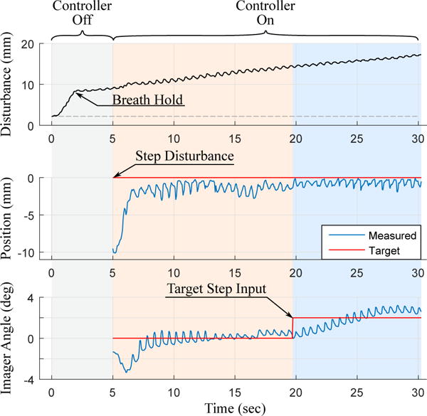
In vivo tests demonstrating the ability of the robotic system to maintain the catheter tip at the target pose despite disturbance step, disturbance ramp, and target step inputs.
The goal of the robotic system in vivo was to quickly navigate the catheter tip and US imager to a target pose, collect images of target structures, and then navigate to the next target pose. The controller was designed to actively converge towards the target pose. US image acquisition was triggered once the catheter reached the target tip pose within a specified error threshold. During the in vivo study images for 4D reconstruction were collected at increments of 2° steps. US images were collected through multiple heart beats and then the catheter was moved to the next target pose with a step input to the target angle. After 80 sweeps the mean position error was 2.0 mm (σ = 1.1 mm), and the mean angular error was 0.65° (σ = 0.51°).
The acquired US images are reconstructed into 3D or 4D volumes to enhance visualization of anatomical structures and working instruments [17]. ECG data is used to gate frames and reconstruct a volume with images that were taken in the same phase of the heart cycle. An example of one reconstructed volume of an ablation catheter (highlighted in blue) in the right ventricle is shown in Fig. 13.
Fig. 13.

In vivo 3D reconstruction of an ablation catheter inserted into the right ventricle.
VI. Discussion
The experimental results from bench top and in vivo studies demonstrated the robustness of the robotic system to converge the catheter tip at desired poses through both desired adjustments (target inputs) and undesired adjustments (disturbance step and ramp inputs due to respiration and other effects). An investigation of timing and accuracy demonstrated that the robot converged to the target pose faster and with more consistent timing when the allowable error threshold was greater. It is possible to navigate the position with sub-millimeter accuracy, but the longer convergence time is not necessarily practical depending on the experimental setting.
VII. Conclusions and Future Work
This work presents a method for robustly and accurately navigating flexible manipulators through unconstrained environments with external disturbances. The control strategy was designed to calculate the configuration space parameters of the catheter based on the current tip pose and base rotation that were measured using two EM sensors. This enabled navigation to be robust to friction and backlash nonlinearities as well as external disturbances to the catheter body. Results during an in vivo animal trial demonstrated accurate navigation and angular control of the US imager despite unmodeled step and ramp input disturbances due to respiratory motion and cyclical disturbances from cardiac motion. US images collected during the in vivo study were reconstructed into 3D and 4D volumes for enhanced visualization of cardiac structures.
Future work on the system includes automatically manipulating the US catheter to track cyclical respiratory motion. The speeds and accuracies demonstrated during unconstrained motion of the catheter tip indicate that it is possible for the catheter to track a cyclical 3D trajectory at the pace of respiratory motion. Once complete, the robotic US catheter steering system will be able to provide enhanced visualizations of cardiac anatomy and working instruments during normal respiratory and cardiac motion.
Acknowledgments
The authors would like to acknowledge Laura J. Brattain, PhD, Yaroslav Tenzer, PhD, and James Weaver, PhD.
This work was supported by the Harvard University John A. Paulson School of Engineering and Applied Sciences, American Heart Association Grant #15PRE22710043, the National Institutes of Health Grant #1R21EB018938, and the NVIDIA Academic Hardware Grant Program.
Contributor Information
Alperen Degirmenci, Email: adegirmenci@seas.harvard.edu, John A. Paulson School of Engineering and Applied Sciences, Harvard University, Cambridge, MA 02138 USA.
Paul M. Loschak, Email: loschak@seas.harvard.edu, John A. Paulson School of Engineering and Applied Sciences, Harvard University, Cambridge, MA 02138 USA.
Cory M. Tschabrunn, Harvard-Thorndike Electrophysiology Institute, Beth Israel Deaconess Medical Center, Harvard Medical School, Boston, MA 02215 USA
Elad Anter, Harvard-Thorndike Electrophysiology Institute, Beth Israel Deaconess Medical Center, Harvard Medical School, Boston, MA 02215 USA.
Robert D. Howe, Email: howe@seas.harvard.edu, John A. Paulson School of Engineering and Applied Sciences, Harvard University, Cambridge, MA 02138 USA; Harvard – MIT Division of Health Sciences & Technology, Cambridge, MA 02139 USA.
References
- 1.Moscucci M, Grossman, Baim’s . Cardiac Catheterization, Angiography, and Intervention. Lippincott Williams & Wilkins; 2013. [Google Scholar]
- 2.Corindus, Inc. CorPath Robotic PCI. [Online]. Available: http://www.corindus.com/
- 3.Catheter Robotics, Inc. Amigo Remote Catheter System. [Online]. Available: http://catheterrobotics.com/images/AmigoBrochure.pdf.
- 4.Stereotaxis. V-Drive Robotic Navigation System. [Online]. Available: http://www.stereotaxis.com/products/vdrive/
- 5.Stereotaxis. Niobe ES. [Online]. Available: http://www.stereotaxis.com/products/niobe/
- 6.Hansen Medical, Inc. Sensei X Robotic Catheter System. [Online]. Available: http://hansenmedical.com.
- 7.Penning RS, Jung J, Zinn MR, Ferrier NJ. An Evaluation of Closed-loop Control Options for Continuum Manipulators. Robotics and Automation (ICRA), 2012 IEEE Int’l Conf on. 2012 May;:5392–5397. [Google Scholar]
- 8.Webster RJ, III, Jones BA. Design and Kinematic Modeling of Constant Curvature Continuum Robots: A Review. Int’l J of Robotics Research (IJRR) 2010;29(13):1661–1683. [Google Scholar]
- 9.Khoshnam M, Azizian M, Patel RV. Robotics and Automation (ICRA), 2012 IEEE Int’l Conf on. IEEE; 2012. Modeling of a steerable catheter based on beam theory; pp. 4681–4686. [Google Scholar]
- 10.Ganji Y, Janabi-Sharifi F, Cheema AN. Robot-assisted catheter manipulation for intracardiac navigation. Int’l J of Comp Asst Radiology and Surgery. 2009;4(4):307–315. doi: 10.1007/s11548-009-0296-z. [DOI] [PubMed] [Google Scholar]
- 11.Camarillo DB, Carlson CR, Salisbury JK. Configuration tracking for continuum manipulators with coupled tendon drive. Robotics, IEEE Trans on. 2009;25(4):798–808. [Google Scholar]
- 12.Seung S, Liu P, Park S, Park J-O, Ko SY. Single-port robotic manipulator system for brain tumor removal surgery: Siromans. Mechatronics. 2015;26:16–28. [Google Scholar]
- 13.Loschak P, Brattain L, Howe R. Automated pointing of cardiac imaging catheters. Robotics and Automation (ICRA), 2013 IEEE Int’l Conf on. 2013 May;:5794–5799. doi: 10.1109/ICRA.2013.6631410. [DOI] [PMC free article] [PubMed] [Google Scholar]
- 14.Kesner S, Howe R. Design and control of motion compensation cardiac catheters. Robotics and Automation (ICRA), 2010 IEEE Int’l Conf on. 2010 May;:1059–1065. doi: 10.1109/ROBOT.2010.5509250. [DOI] [PMC free article] [PubMed] [Google Scholar]
- 15.Loschak PM, Tenzer Y, Degirmenci A, Howe RD. A 4-DOF Robot for Positioning Ultrasound Imaging Catheters. Proc of the ASME 2015 Int’l Design Eng Tech Conf & Comp and Info in Eng Conf IDETC/CIE. 2015 Aug; doi: 10.1115/DETC2015-47693. [DOI] [PMC free article] [PubMed] [Google Scholar]
- 16.Loschak PM, Degirmenci A, Tenzer Y, Howe RD. A 4-DOF Robot for Positioning Ultrasound Imaging Catheters. ASME Journal of Mechanisms and Robotics. 2015 doi: 10.1115/DETC2015-47693. [DOI] [PMC free article] [PubMed] [Google Scholar]
- 17.Brattain LJ, Howe RD. Medical Image Computing and Computer Assisted Interventions – MICCAI 2011. Springer; 2011. Real-Time 4D Ultrasound Mosaicing and Visualization; pp. 105–112. [DOI] [PMC free article] [PubMed] [Google Scholar]