
Fig. 5. Design of the MFS measurement head.
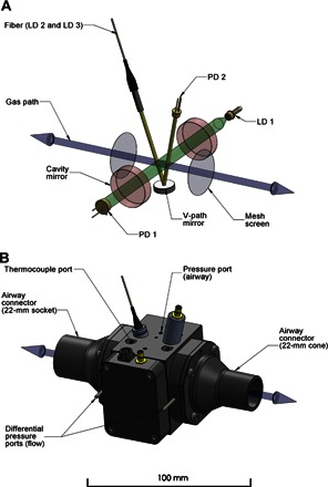
(A) Simplified diagram of the multichannel absorption spectrometer and the pneumotachograph contained within the measurement head. The bidirectional gas path (blue) is shown along with the two mesh screens (gray), across which the pressure drop related to the respiratory flow is measured. Radiation from the 764-nm diode laser (LD 1) used for probing oxygen is injected into an optical cavity constructed from a pair of highly reflective mirrors (red) and collected by a photodiode (PD 1) positioned along the optical axis (green). Two diode lasers, LD 2 and LD 3, located in the drive unit are used to probe for carbon dioxide and water vapor at 2004 and 1368 nm, respectively. Their outputs are spatially combined by a fiber-optic multiplexer located in the drive unit and are transmitted through a hybrid cable into the measurement cell. A fiber-optic collimator launches the radiation into the V path (yellow) and onto the photodiode (PD 2) via a concave mirror. (B) Three-dimensional CAD model of the measurement cell. The differential pressure ports located on the outer sides of the mesh screens are shown, together with the ports for the thermocouple probe and airway pressure sensor.