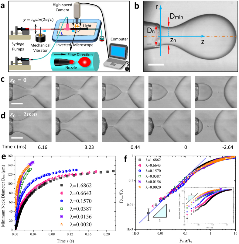
Figure 1. Neck pinch-off in microfluidics.
(a) Experimental setup. (b) Image of a drop discharged from ejection nozzle. Dn, Dmin and Z0 are the nozzle diameter, minimum neck diameter and location of the minimum neck, respectively. Scale bar, 100 μm. (c,d) Snapshots of (c) unperturbed and (d) perturbed neck thinning versus time τ remaining to pinch-off (see supplementary Movies S1,S2,S3,S4,S5). In time period 0 < τ < 6.16 ms before pinch-off, the difference in neck diameter for perturbed case (ε0 = 2 mm) is larger than that for unperturbed case, showing the enhancement of pinch-off by mechanical perturbation. A suction of inner fluid towards the nozzle in (d) characterizes the last stage of neck pinch-off modulated by perturbation. The viscosity ratio of fluid system is λ = 0.157. Inner and outer fluid flow rates are Qi = 0.3 mL h−1 and Qo = 1 mL h−1, respectively. Scale bars, 100 μm. (e) Plot of minimum neck diameter Dmin
versus time τ for unperturbed two-fluid pinch-off with various viscosity ratios. Neck thins faster for fluid system with smaller viscosity ratio. (f) Scaling law for unperturbed neck pinch-off with different viscosity ratios. In Stokes regime, linear scaling gives  . Inset: minimum neck diameter Dmin
versus time τ plotted in a log-log plane. The error comes from the limiting resolution in the captured image.

