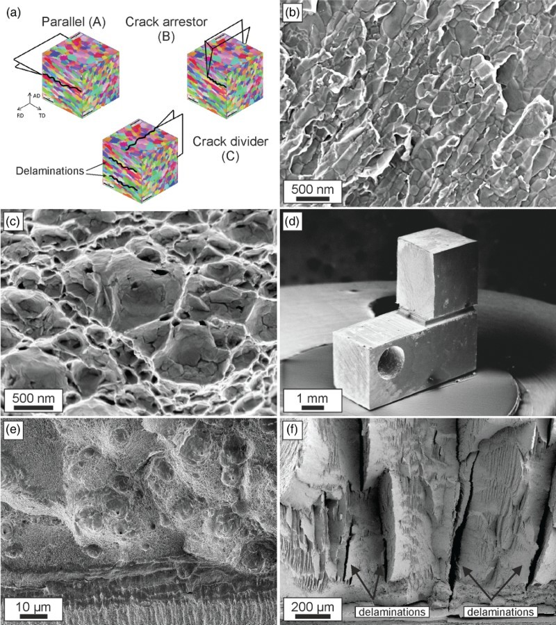
Figure 2.

Overview describing the fracture behavior of UFG-iron and nickel. (a) Principal crack planes and crack growth directions investigated for both materials. For simplicity, the crack plane and crack propagation direction of a specimen orientation are abbreviated as A, B or C. Fractographs for crack growth along the elongated microstructure in iron with intergranular fracture (b) and nickel exhibiting transgranular micro-ductile fracture (c). (d) Iron fracture sample with crack-arrestor orientation. (e) Micro-ductile fracture surface found in Ni for the third testing direction. (f) Fracture surface exhibiting various delaminations (some of them are indicated with arrows) typical for iron for the third orientation (crack-divider orientation).
