Fig. 1.

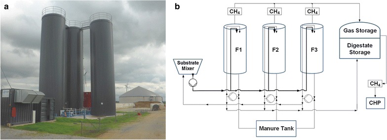
Picture (a) and flow chart (b) of the sampled thermophilic biogas plant. a Left side central heating and power plant; middle the three main fermenters; right side unheated effluent tank

Picture (a) and flow chart (b) of the sampled thermophilic biogas plant. a Left side central heating and power plant; middle the three main fermenters; right side unheated effluent tank