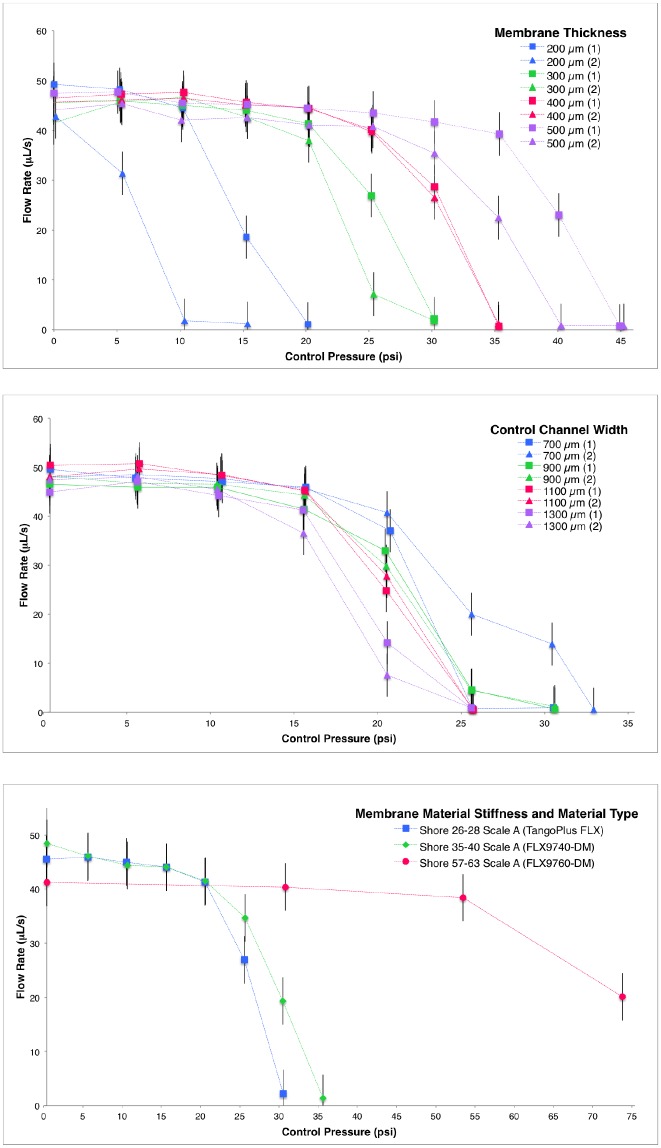
Fig 3. Fluid flow under various conditions.
Measurements of fluid flow through the 3D printed multimaterial valve with varying applied pressure to the control channel are plotted. Dimensions and materials were varied according to Table 1, with a standard membrane thickness of 300 μm, control channel width of 800 μm, control channel height of 800 μm, and a semi-circular flow channel radius of 400 μm. Proportional control of the flow rate is demonstrated and the design parameters are explored through varying membrane thickness (top), control channel width (middle), and membrane material (bottom). Connecting lines are shown only for visualization and the charted points and error bars represent the measured data. For membrane thickness and control channel width, two prints of each design file were tested and each is plotted using the average of two trials per print. The bracketed number in the legend indicates a different print of the same design file and both are plotted for clarity with the same color. Membrane material type tests used a single print. Error bars show repeatability between trials at the same pressure for different prints of the same valve specifications (± 4.4 psi, calculated with 95% confidence interval). Listed stiffness values for the membrane material are sourced from Stratasys, Ltd. Material data sheets [25]. Please see the Supporting Information for all of the data from the trials.

