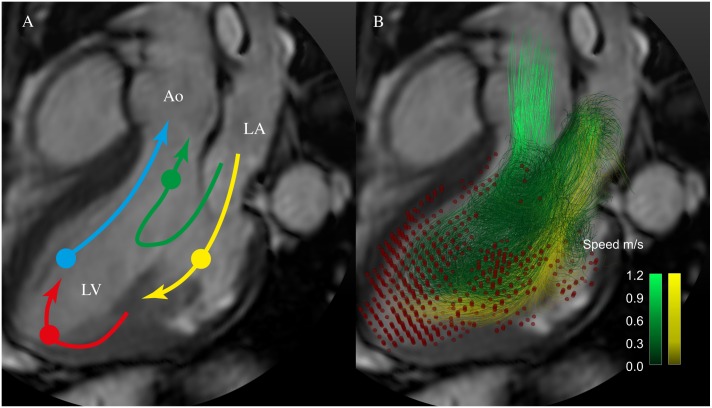
Fig 1. 4D flow components.
A. Schematic of the routes of the four LV flow components; direct flow (green), retained inflow (yellow), delayed ejection flow (blue), and residual volume (red). A semitransparent grayscale three-chamber image provides morphological orientation. Circles indicate the approximate location of the center of mass of each component at the time of end-diastole. B. Particle trace pathlines indicate routes of direct flow (green) and retained inflow (yellow). Red dots indicate the positions of the residual volume pathlines at end-diastole. Non-ejected flow comprises the retained inflow and the residual volume. Ao, aorta; LA, left atrium; LV, left ventricle.

