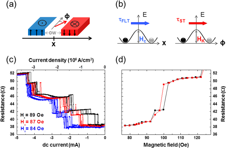
Figure 2. Action of the different spin-torques on the magnetic domain wall.
(a) Illustration of the domain wall and its coordinates in a track. The domain wall position is defined by x, ϕ is its internal tilt angle. (b) Schematic representation of the energy landscape for a domain wall depinned by the Field-like-torque (left) and the Slonczewski torque (right). Hc is the depinning field intrinsic to the pinning center, and HK is the domain wall anisotropy field. (c) Resistive changes during current driven domain wall depinning from a given pinning center (resistance value of 38 Ω) for different values of the external magnetic field in the range [78–92] Oe. (d) Resistive changes during field (parallel to the z-axis) driven domain wall depinning from the same pinning center. The measurement has been done twice.

