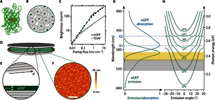
Fig. 1. Laminated eGFP-filled high-Q microcavity used for polariton lasing.

(A) Molecular structure of eGFP with the fluorophore in the center surrounded by 11 β sheets. (B) Schematic of how the β sheets prevent concentration quenching. (C) Normalized brightness versus pump fluence of thin films of solid-state eGFP and of the synthetic organic polariton material TDAF. Bimolecular exciton-exciton annihilation reduces spontaneous emission at high pump fluence (linear intensity increase changes to sublinear increase with slope 1/2). eGFP tolerates 20-fold higher pump fluence before the annihilation-induced sublinear behavior sets in. (D and E) Schematic illustration (D) and cross section of the microcavity containing a 500-nm-thick film of solid-state eGFP (E). The top mirror is slightly wedged with respect to the bottom mirror to allow adjustment of the cavity resonances by tuning the total cavity thickness d. (F) Atomic force microscopy topography map of the spin-coated GFP layer. Scale bar, 5 μm. (G) Absorption and emission spectrum of a solid-state eGFP film. The blue dashed lines indicate the two pronounced exciton resonances. The gray area marks the region over which gain is observed in eGFP [from the study by Dietrich et al. (23)], and the yellow region marks the range of polariton lasing (see Figs. 3 and 4). (H) Dispersion relation for uncoupled photonic modes (gray dotted lines) and strongly coupled polariton modes (green solid lines), calculated for typical cavity dimensions using a transfer matrix algorithm. UP, upper polariton branch; MP, middle polariton branch; LP, lower polariton branch.
