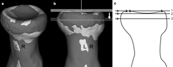
Fig. 1.
a Aligned 3D models of right (R) and left (L) proximal radii. b 3D models of the proximal R and L radii with a cross-sectional plane. This plane was positioned at the widest level parallel to a reference plane fitted tangentially to the three most proximal points (asterisk symbol) on the proximal radial head surface. c Scheme of the proximal L and R radii with a reference plane (1) and the parallel cross-sectional planes to cross-section the radius head at the level of the trough (2), and at the widest level (3) of the radial head

