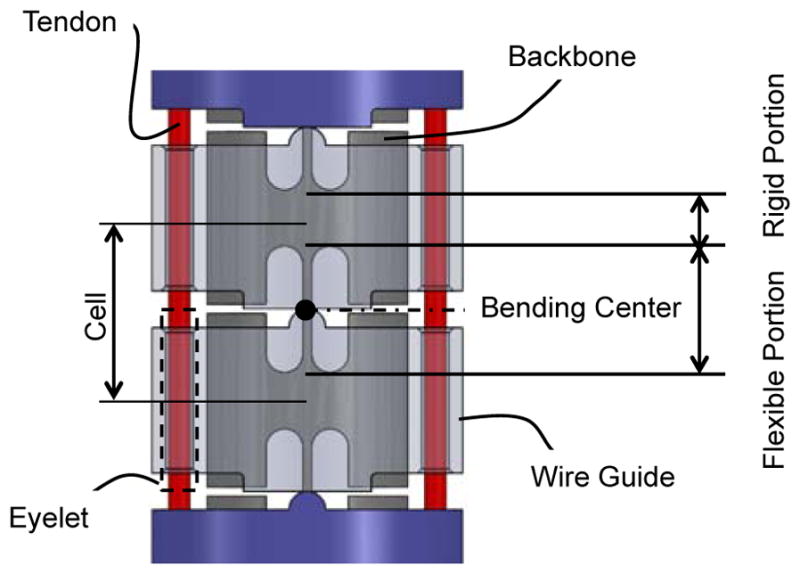
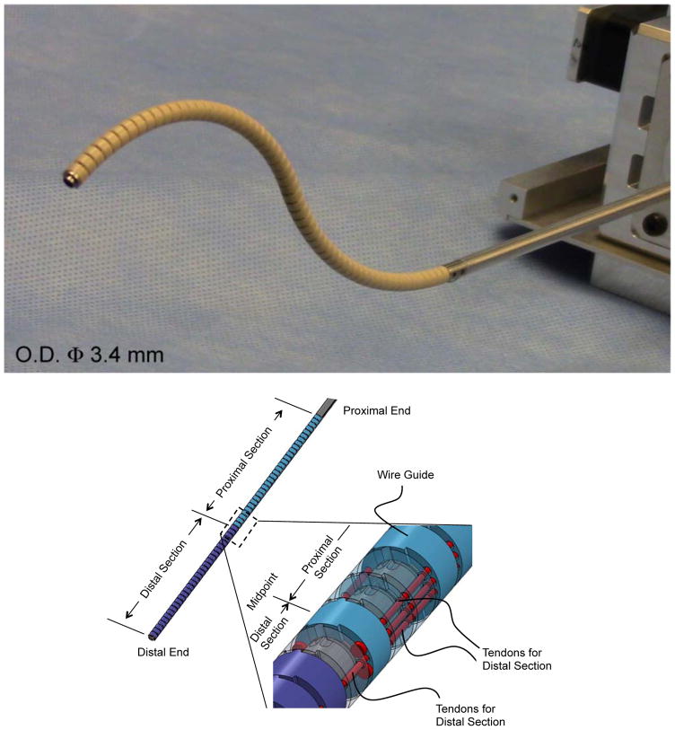
Fig. 1.

Tendon-driven continuum robot. (Top) Perspective view of the tendon-driven continuum robot. (Center) Perspective view of the component formation of the robot. The robot comprises two bending sections, i.e. the distal and the proximal sections. Two pairs of three tendons run through the wire guides. One antagonistic pair of tendons is terminated at the distal end. Two antagonistic pairs of tendons are terminated at the midpoint of the robot. (Bottom) Side view of the cascaded spring system. The wire guides are made of polyether ether ketone (PEEK), and the backbone is monolithically machined from super elastic TiNi alloy (Nitinol) with laser cutting. The hinges of the wire guides are aligned with the bending center of the flexible portion in the backbone by stacking the wire guides without an additional alignment process

