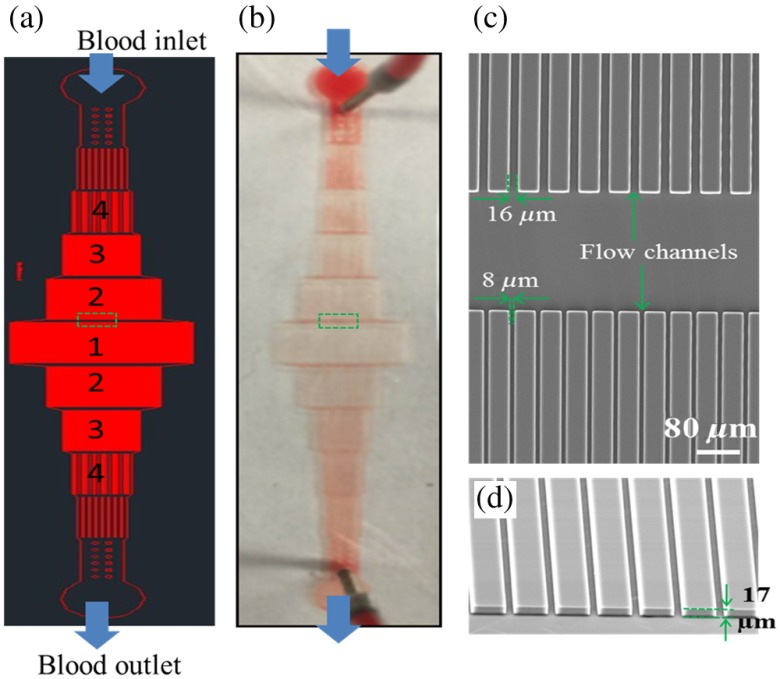
Fig. 1.
Schematic and photographs of the microfluidic chip. (a) Photomask for the fabrication of the microfluidic chip. The widths of the channels in the regions 1, 2, 3, and 4 are 8, 16, 32, and , respectively. (b) Photography of an actual microfluidic chip. (c) Scanning electron microscope (SEM) image of the chip corresponding to the region in the green dash box in a. (d) The tilted SEM image of the flow channels. The height of the channels is .

