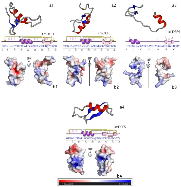
Fig 2. Homology modeling of LmDEFs.
a, Representation of the homology-derived solution structure of LmDEFs (a1-a4). α-helix (red), strand or β-sheet (blue), and coil (gray); the images were optimized with the Protein Picture Generator v1.21. Secondary structure elements were predicted with ProFunc server at EMBL-EBI; key: Helix-Strand: purple; helices labelled H1, H2,…and strands by their sheets A, B,…Motifs: β beta, turn γ gamma turn, and beta hairpin (red arch). Disulfide bond (1–1, 2–2, 3–3). b, Electrostatic potential distribution on the peptide surfaces (b1-b4). Positive potential is shown in blue, and negative potential is in red; the contouring value of the potential is in kT/e; the bar at the bottom (-5 to +5). The images were drawn using PyMOL Molecular Graphics System (DeLano Scientific, San Carlos, CA).

