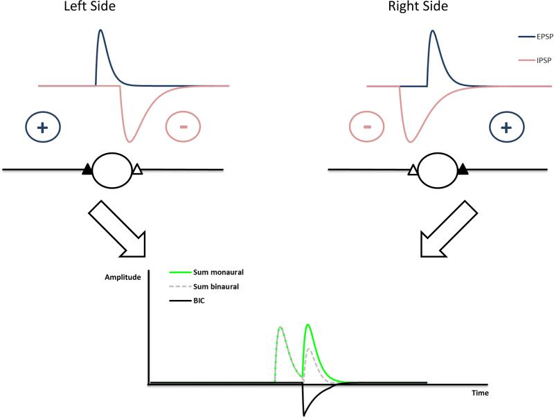
Figure 4.
Circuit underlying the generation of the BIC based on neurons integrating excitatory inputs from the ipsilateral side and inhibition from the contralateral side. In the example, the stimulus reaches the left ear earlier than the right ear (ITD). The ITD will shift the relative timing of excitatory and inhibitory inputs. In this circuit, the DN1 component will show a latency shift of ΔITD with an increase of ΔITD. If spike probabilities are taken into account, the latency shift can be smaller (Ungan et al. 1997).

