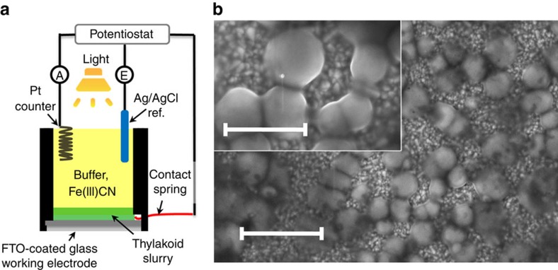
Figure 1. The BPEC cell.
(a) Schematic illustration of the BPEC cell. The cell comprises a cylindrical container with a window at the bottom, where a transparent working electrode (FTO coated glass) serving as the anode is sealed against a rubber gasket. The anode is electrically connected through a contact spring to a potentiostat, which is set in three-electrode mode (except for the two-electrode measurements described towards the end of the article), along with an Ag/AgCl reference electrode and a Pt counter electrode (that is, cathode). The potentiostat measures the current between the working and counter electrodes using an ammeter {A}, and the potential {E} of the working electrode with respect to that of the reference electrode. A minimal amount of thylakoids settles from a slurry of crude spinach thylakoids in buffer solution containing glycerol onto the exposed area (1.08 cm2) of the FTO anode. The cell cavity is filled with 20 ml buffer A solution, containing the redox mediator Fe(III)CN (K3Fe(CN)6), which serves as a recyclable electron shuttle between the thylakoids and the anode. (b) Scanning electron microscopy image of the spinach membranes on the surface of a FTO coated glass electrode. Small amount of membranes were placed on the electrode and the scanning electron microscopy images were taken in vacuum. Scale bar, 2 μm. Inset: scanning electron microscopy image at higher magnification. Scale bar, 1 μm.

