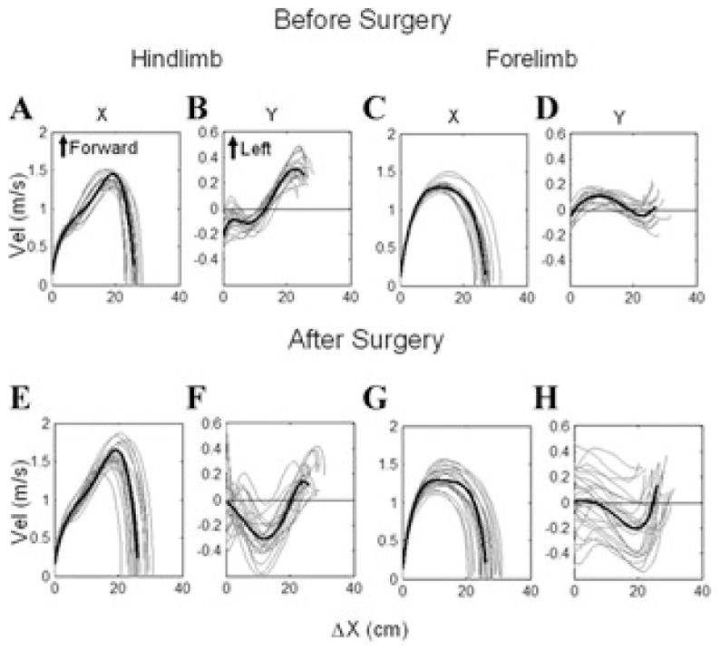
Figure 4.

Phase plane plots of the right hindlimb (A, B, E, F) and right forelimb (C, D, G, H) swing phase velocities (C, D, G, H) before (A–D) and after (E–H) all six semicircular canals were plugged. The position of the limbs along the X-axis is shown on the abscissae, plotted against the X-axis velocity in A, C, E, G, and against the Y-axis velocity of the limbs in B, D, F, H. Note the broadened endpoints of the swing-phase X-axis velocities in E, G, and the dispersion of the Y-axis velocities in F, H after the semicircular canals were plugged.
