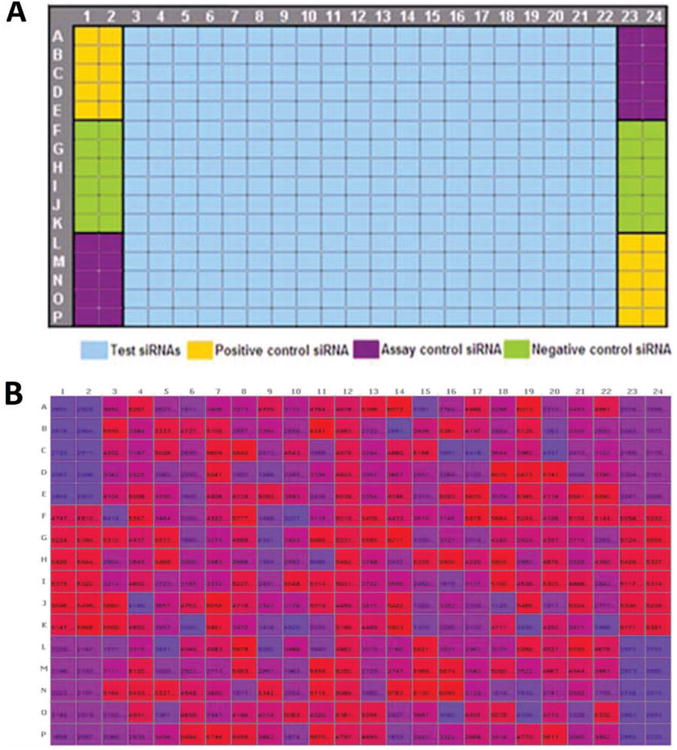
Figure 3.

Plate format showing layout of controls after extensive troubleshooting. (A) Plate template with controls on both sides of the plate, increasing the number of control wells. Negative control (scrambled siRNA) is strategically placed in the center wells of the column to minimize edge or corner effect. (B) Heat map of raw values from a 384-well plate showing eradication of edge effect following troubleshooting and change of plate format.
