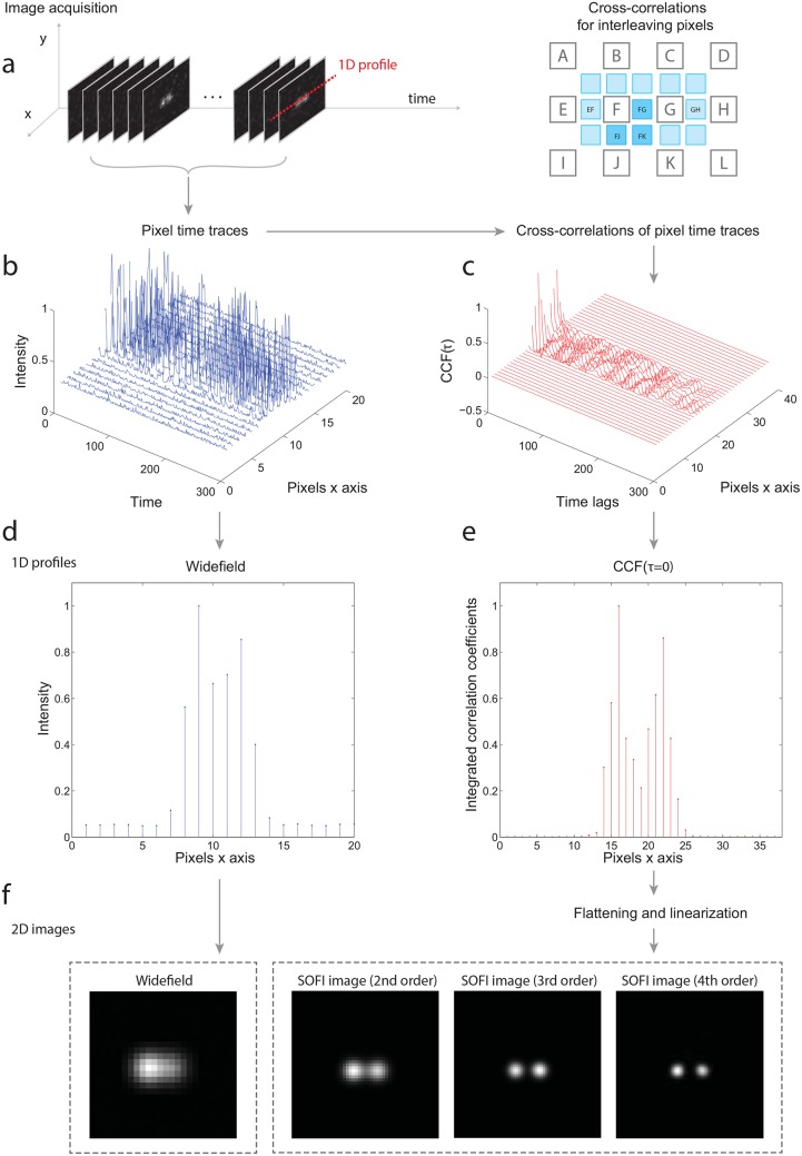
Fig 1. The SOFI principle in a one dimensional example.
(a) 1D profile is taken from the input image sequence of two blinking emitters. (b) Corresponding 1D intensity time traces. (c) 2nd order cross-cumulants calculated from the intensity time traces for all time lags. In practice, mainly the zero-time lag (τ = 0) is used. Using cross-cumulants, the interleaving pixels are also calculated. Note that the 2nd order cross-cumulant is equivalent to cross-correlation. (d) The widefield image (the temporal average of intensity time traces). (e) The 2nd order cross-cumulants for τ = 0. (f) The resulting 2D SOFI images up to the 4th cumulant order after flattening and linearization.

