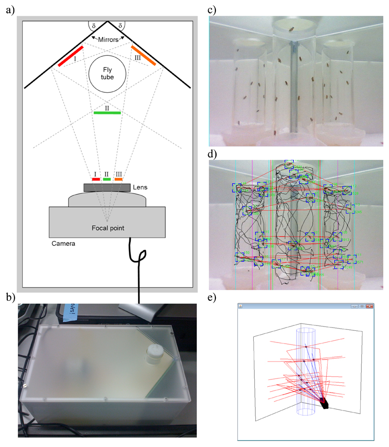
Figure 1. Scheme of the iFly apparatus.
(a) Scheme of the fly chamber with test tube, camera, and mirrors placed at angle δ; the three perspectives (I, II, and III) are projected onto the camera lens. (b) Image of fly chamber, showing how a test tube with flies can be inserted through a hole in the frosted plastic lid. (c) Snapshot from the graphical user interface (GUI) showing live video stream. The GUI contains components that allow the user to adjust parameters for the iFly chamber, camera, and image segmentation algorithm. (d) Example of a captured frame with results from the image segmentation algorithm overlaid; trajectories (black lines) and current fly positions (green circles and blue corners), from which the Cartesian coordinates of the trajectories of the flies are extracted, are shown, together with red lines that connect fly images predicted to be projections originating from the same fly. (e) Real-time three-dimensional reconstruction of the ray tracing calculations for visual control during image analysis. Images reflected by two mirrors are triangulated with the direct image to accurately locate the flies in the tube; camera (black box), tube (blue cylinder), mirrors, and fly positions (black dots) are shown, with direct rays drawn in blue, and those reflected on mirrors in red.

