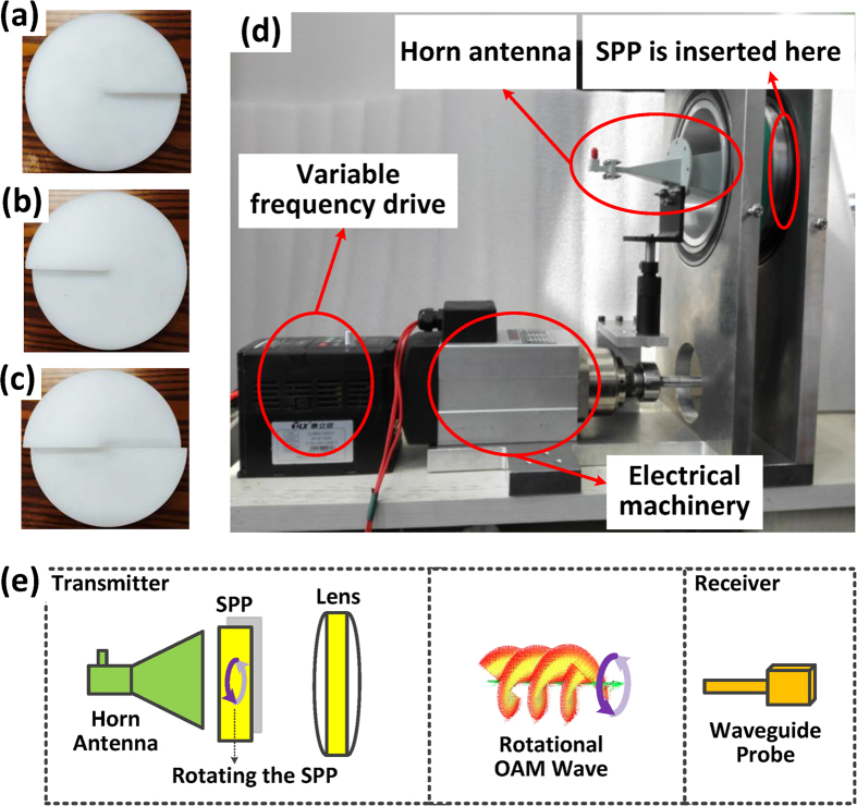
Figure 1. Transmission structure with a rotational OAM wave.
(a) Spiral phase plates with OAM l = −1. (b) Spiral phase plates with OAM mode l = +1. (c) Spiral phase plates with OAM mode l = +2. (d) The prototype of the transmitting antenna to generate the rotational OAM wave. (e) Schematic of the transmission with the rotational OAM wave.

