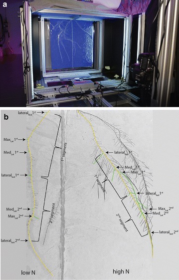
Fig. 2.

a Imaging car subunit which facilitated analysis of the root system. The root system on a split-root rhizoslide was placed approx. in 1 m distance to the 24 megapixel DSLR-camera. LED bars were placed between camera and rhizoslide on the right and left side, respectively. b Root system developed on one side of the rhizoslide and treated with a split-nitrogen application 10 days after solution change. Roots highlighted in yellow are the crown roots which were used in this example image to investigate crown root growth. Waved brackets indicate the two segments used to investigate the number of lateral roots and the medium (MedLat) and longest (MaxLat) lateral root length in the first (MedLat 1st, MaxLat 1st) and in the second (MedLat 2nd, MaxLat 2nd) segment. The first segment started at the position of the the last developed lateral root (lateralfirst1st) at solution change and the second segment continued after the first segment (laterallast1st). The lateral roots used to investigate the medium and longest lateral root length in the two segments are highlighted in green
