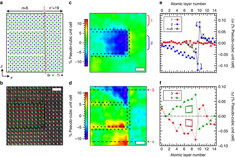
Figure 5. Distortion of new polar phases near a (SrO)2 stacking fault in Sr7Ti6O19.
(a) Model structure of a stacking fault for the n=6 Srn+1TinO3n+1 RP structure. To the left of the stacking fault (red dashed line) is the n=6 structure while to the right is a perovskite slab of the n′=19 structure. The strontium and titanium atoms are given by green circles and blue diamonds, respectively. (b) Drift-corrected HAADF image of a stacking fault. Superimposed arrows qualitatively show the SrO and TiO2 layer dipole moment near the stacking fault (c,d) Colour map of difference between atomic positions of the model and HAADF-STEM derived cation positions perpendicular Δx (panel c) and parallel Δz (panel d) to the stacking fault. The Δx and Δz maps show that the accommodation of the lattice mismatch between the n=6 and n′=19 structure near the stacking fault is predominantly contained within the n=6 region. The (SrO)2 rock salt layers are indicated by the black open circles. (e) Line profile of Δx (filled red circles) taken along the horizontal dashed line labelled (1) in panel (c) and its comparison to an ideal n=6 structure across the rock salt layer (open blue squares) highlight an ∼10 pm shift of the rock salt leading to a compressive strain in the n=6 layer. (f) Line profile taken along the dashed horizontal line labelled (2) in panel (d) from selected region #2 in (d) showing a monoclinic-like distortion (inset schematic) of the SrTiO3 pseudo-cubic unit cell across the stacking fault. Scale bar, 1 nm.

