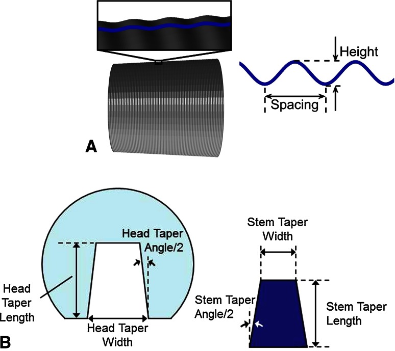
Fig. 1A–B.
(A) Schematic showing the stem taper surface topography consisting of parallel machining marks. The machining marks are characterized as a wave that can be represented by height and spacing parameters. (B) Schematic of head and stem tapers showing global dimensions that were measured with a digital caliper. Head and stem taper angles were measured with a coordinate measuring machine.

