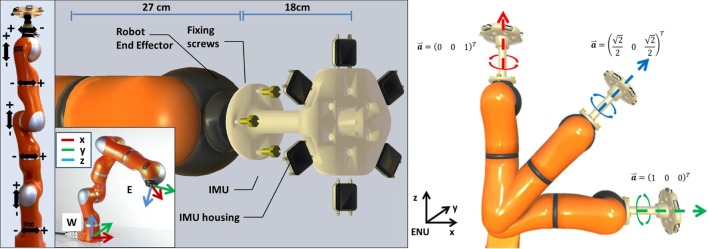
Fig 1. The figure illustrates the experimental setup used for performing the accuracy assessment.
From the left to the right the figure display: a view of the robotic arm, where all the 7 DoF axes are indicated; the definition of the world (W) and the end-effector (E) coordinate frames of the robot; the custom tool devised with the fixation mechanism used to rigidly attach the 6 IMUs to the robotic system; the 3 different configuration of the robotic arm used in the experimental protocol.

