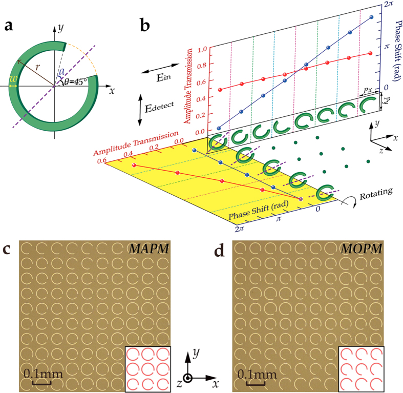
Figure 2. Basic functional units and partial optical images of the metasurfaces.
(a) Schematic of a CSRR with outer radius r, width w, opening angle 2α, and orientation angle θ with respect to the x-axis. (b) Simulated transmission amplitude modulation and phase shift of the CSRRs at 0.8 THz according to their r, α and θ parameters. The transmission electric field is y-polarized and the incidence is x-polarized. The periodicity of the unit cell along x and y direction is Px = 80 μm and Py = 80 μm, respectively. For the upper eight CSRRs in the white graph, r and α are varying, while θ remains 45° or −45°. For the five CSRRs in the yellow graph, however, r and α remain constant and θ is varying, where the amplitude follows a |sin(2θ)| dependence with the phase shift remaining invariant. The purple dash lines represent the symmetry axis of the CSRRs. The nine green dots in the middle are the apostrophes representing that similar rotation rules illustrated in the yellow graph also apply to the other seven CSRRs in the white graph. (c) Partial optical image of MAPM with both a five-level amplitude modulation and an eight-level phase modulation. (d) Partial optical image of MOPM with an eight-level phase modulation and a constant amplitude. The insets on the lower right of c and d represent the designed sizes of CSRRs.

