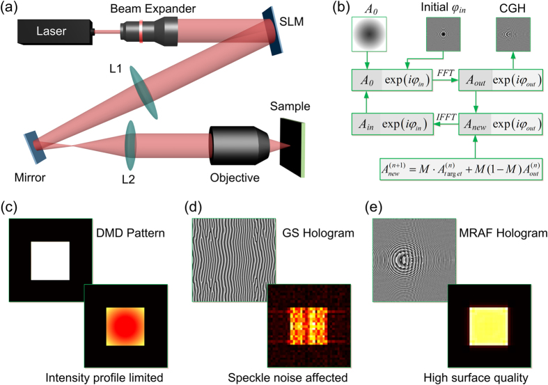
Figure 1. Fabrication setup and CGH calculation of MHP method.
Schematics of intensity distribution by DMD, GS-CGH and MRAF-CGH based single exposure approach. (a) Schematic diagram of experiment setup of the MHP approach based on SLM. The SLM is placed at the back focal plane of L1. The focal length of L1 is 600 mm and that of L2 is 200 mm. L1, L2 and objective are confocal. (b) Flow-chart diagram of MRAF algorithm. The differences between MRAF and GS algorithms are “initial phase” and “new field in output plane”. (c) Single-exposure laser direct patterning by DMD. The optical intensity distribution at the focal plane is Gaussian due to the profile of incident Gaussian beam. (d) Single-exposure holographic femtosecond laser direct patterning by GS algorithm. The optical intensity distribution at the defocused plane can be designed as a complex rectangle by GS algorithm calculated CGH. (e) Single-exposure holographic femtosecond laser direct patterning by MRAF algorithm. Compared with GS algorithm, the optical intensity distribution at the focal plane is significantly improved.

